
Model Number: TPT22S12A-FLKS
Input Voltage: 100~240Vac
Output: 12V1.8A
Working Temperature: -33 to +45°C
Size: 104mm*48mm*28mm
Single Output
Efficiency: >83%
Output Protection: OVP/OSP/OCP/OLP
RoHS Compliant
lEC 60950/62368
EMI Class B
Leakage Current: Less than 3.5mA
Surge: Common mode 6KV, differential mode 6KV
General rules:
This product is AC to DC power supply, 90~264V AC input, single output +12V, total output power 21.6W, through
CQC, TUV (CB) certification, in line with the EU RoHS directive.
1. Electrical characteristics
1.1 Input characteristics
1.1.1 Basic input characteristics
Project | unit | Minimum | Typical value | Max | Remarks |
AC input voltage range | Vac | 90 | 110/220 | 264 | |
Safety certification voltage | Vac | 100 | / | 240 | |
AC input voltage frequency | Hz | 47 | 50/60 | 63 | |
Input Current | A | / | 0.4 | 0.5 | 110 Vac input, full load; |
Inrush current | / | / | / | / | The surge current should be less than the specifications of key components (such as rectifier bridges, fuses, etc.). Repeated switching of the power supply will not cause damage to the power supply or blown fuse. |
AC input system | / | / | Single-phase input | / |
1.1.2 Input protection feature
Project | unit | Minimum | Typical value | Max | Remarks |
Input overcurrent protection | / | / | / | / | The AC input lines (L, N) have fuses to meet the requirements of dual live wires |
Input under-protection | V | / | 65 | 80 | The AC input is lower than the protection point voltage and no output, it can work normally after returning to the normal grid. |
1.2 Output characteristics
1.2.1 Basic output characteristics
Project | unit | Minimum | Typical value | Max | Remarks | |
Output Power | W | / | 21.6 | / | 90Vac~264Vac | |
Output voltage range | +12V | Vdc | 11.4 | 12.0 | 12.6 | |
Output current range | +12V | A | 0 | / | 1.8 | |
Full load output efficiency | % | 83 | / | / | 115/230Vac input, rated load current (heat engine for more than half an hour when testing efficiency) | |
Load loss | W | / | 0.2 | 0.3 | ||
Stabilization accuracy | +12V | % | / | / | ±5 | Full voltage input range, full load output |
Linear adjustment rate | % | / | / | ±2 | Rated 10%~100% load output, full voltage range change | |
Load Adjustment rate | % | / | / | ±3 | Rated voltage input, 10%~100% load change | |
Noise + ripple (Peak-to-peak value) | +12V | mV | / | / | 120 (240) | It is carried out in the range of 90~264V input voltage and load, and the output terminal is tested with a 0.1µF ceramic or gold film capacitor and a 10µF electrolytic capacitor. The bandwidth of the oscilloscope is 20MHz; 1. Under normal temperature and high temperature: 120mV, 2. Under -33℃~-10℃ ambient temperature: 240mV |
Dynamic response overshoot | % | / | / | ±5 | 25%~50%~25% or 50%~75%~50% load change, current change rate 0.1A/µS, cycle 4mS; | |
Switch overshoot | % | / | / | ±5 | ||
Power on time | S | / | / | 3 | T1≤3S, see Figure 1 | |
Output rise time | mS | / | / | 200 | The output voltage rises from 10% to 90%, T2≤200 mS | |
Power-down sustaining time | mS | 10 | / | / | T3≥10mS | |
Capacitive load | +12V | µF | / | / | 2000 | Full input voltage, full load range test |
Figure one")
1.2.2 Output protection features
Project | unit | Minimum | Typical value | Max | Remarks | |
Output overvoltage Protection point | +12V | Vdc | 13.5 | / | 16 | |
Output overcurrent Protection point | +12V | A | 2.2 | 2.7 | 3.5 | The power supply is in hiccup protection |
Output short circuit protection | / | / | / | / | When the output terminal of the power supply is short-circuited to ground, the power supply can be automatically protected; after the short-circuit is removed, the power supply can be automatically restored. | |
2. Environment
Project | unit | Minimum | Typical value | Max | Remarks |
Operating temperature | ℃ | -33 | 25 | 45 | -40℃ storage 48 hours power can be started |
Storage temperature | ℃ | -40 | 25 | 85 | |
Working humidity | % | 5 | / | 95 | No condensation |
Altitude | m | 0 | 0 | 5000 | High temperature derating under 3000~5000m operating environment conditions, the maximum working stability is reduced by 1℃ for every increase of 200m |
Storage environment height | m | 0 | 0 | 15250 |
3. Electromagnetic compatibility
ITEM | INDEX REQUIREMENTS | SDANDARD |
Conducted interference(CE) | Level B | CISPR 22 |
Radiation interference(RE) | Level B | CISPR 22 |
AC port(CS) | 0.15~80MHz:10V【80%AM(1kHz)】;(Criterion A) | IEC61000-4-6 |
Radiation immunity(RS) | 80~1000MHz:10V/m【80%AM(1kHz)】; 1400~2700MHz:10V/m【80%AM(1kHz) 】 (Criterion A) | IEC61000-4-3 |
Whole machine port ESD |
Contact discharge: 8kV (level B); air discharge: 15kV (level B) | IEC61000-4-2 |
AC port EFT/B | Index: 2kV (criterion B) | IEC61000-4-4 |
AC port DIP | Drop to 0%, time 10ms; 0%, time 20ms; drop to 70%, time 500ms; drop to 0%, time 5000ms; (criterion B/B/B/C); | IEC61000-4-11 |
AC current harmonics | Rated voltage class A | IEC61000-3-2 |
AC voltage fluctuations, Flashing | Pst value is not greater than 1; Plt value is not greater than 0.65; The relative voltage change dc does not exceed 3.3%; The maximum relative voltage change dmax does not exceed 4%; During the voltage change, the time when the d(t) value exceeds 3.3% is not more than 500ms. | IEC61000-3-3 |
Surge | Differential mode 6kV, 2 ohms; common mode 6kV; 2 ohms, 1.2/50 (8/20) us mixed wave; criterion ITU-B | ITU-T K.44 |
4. Safety regulation
ITEM | GRADE | STANDARD (TEST CONDITIONS) |
Input to output | 3000Vac | Lasts for 1 minute, no breakdown, no flashover phenomenon, leakage current <10mA (output is not grounded) |
Input to ground | 1500Vac | Lasts for 1 minute, no breakdown, no flashover phenomenon, leakage current <10mA, remove GDT |
Insulation resistance | 10MΩ | Under normal temperature and pressure, the relative humidity is 90℅, and the test voltage is DC 500V, the insulation resistance of the AC part and DC part of the main circuit of the rectifier to the ground, and the insulation resistance of the AC part to the DC part are not less than 10MΩ. |
Leakage current | Class I:≦3.5mA | Input 264VAC/50Hz. |
Note: The gas discharge tube needs to be disconnected during the test.
5. Reliability
MTBF: 100,000 hours, working at an ambient temperature of 25°C and the rated power grid and load.
E-CAP: 5 years, working at an ambient temperature of 40℃ and rated power grid and load.
HALT test:
sequence | Test items | Test Conditions | Analyzing conditions |
1 | HALT low temperature step stress test | The temperature of the sample starts from -10°C, and the temperature is reduced in steps of 10°C. The temperature point reached after stepping is called the temperature step; first, the test sample is powered off, the test box begins to cool down, and after reaching the set temperature of the test box, it stays For more than 20 minutes, ensure that the inside of the chip is completely cold; power on the test sample, monitor the performance of the sample, and judge whether the startup is successful according to the performance index, and each temperature point should conduct a low-temperature startup test. The input voltage requirement for low temperature start is the highest and lowest input voltage, and the load is the maximum rated load. The residence time of each temperature step should be long enough (15-20 minutes after the product temperature reaches the temperature set point), so that the temperature of each device of the product is stable; at the same time, the predetermined test items (regulation accuracy, short-circuit function) should be completed , Switch machine test, communication function), and record data. During the temperature change process and after the functional test of each temperature step is completed, power-on and power-off must be performed at least 3 times. The input voltage of power-on and power-off is required to be the highest and lowest input voltage, and the load is the maximum output load. If the product fails and the temperature rises to the previous temperature step, it is judged whether the fault is the operating limit or the destruction limit; if it is determined to be the operating limit, the specific operating limit is precisely defined by using 5°C as the step length. | Failures that occur within -33°C must be modified, and root causes must be analyzed for failures within [-33°C to -50°C] |
2 | HALT high temperature step stress test | The sample starts at 60°C, and the temperature rises step by step, and the step length is 10°C; the residence time of each temperature step should be long enough (15-20 minutes after the product temperature reaches the temperature set point), so that the temperature of each device of the product Stabilize; At the same time, it is guaranteed to complete the predetermined test items (regulation accuracy, short circuit function, switch machine test, communication function), and record the data. During the temperature change process and after the functional test of each temperature step is completed, power-on and power-off must be performed at least 3 times. The input voltage of power-on and power-off is required to be the highest and lowest input voltage, and the load is the maximum output load. If the product fails and the temperature drops to the previous temperature step, it is judged whether the failure is the operating limit or the destruction limit. If it is determined as the operating limit, use 5℃ as the step length to accurately define the specific operating limit | Failures that occur within 110°C must be corrected, and root causes must be analyzed for failures within [110°C to 130°C] |
3 | HALT vibration step stress test | The initial vibration of the random vibration step test is 10 Grms, and the step length is 10 Grms. After it is greater than 30 Grms, the step length is adjusted to 5 Grms. Each vibration step stays for 15 minutes to ensure the completion of the predetermined test items (regulation accuracy, short circuit function, switch test, communication function), and record the data | Failures that occur within 30Grms of vibration must be corrected, and failures that occur outside of 30Grms must be analyzed for the root cause |
4 | HALT comprehensive stress test | Vibration limit value: the vibration operating limit found in the random vibration stepping test *90%; High and low temperature range: [High and low temperature cycle low temperature point] = (Low temperature operation limit -25°C) × 80% + 25°C; [High and low temperature cycle high temperature point] = (High temperature operation limit -25°C) × 80% + 25°C ; | The test sample must fail. If two complete comprehensive stress test cycles are carried out and the test sample still has no failure, the test can be stopped. |
Environmental test:
Sequence | Test items | Test Conditions | Analyzing conditions |
1 | High temperature and humidity Hot storage | The test box stays at 40°C (humidity between 90% and 95%) for 96h; | After the test, the material is not deformed, and the module should not be damaged or have abnormal performance (you can only check the default output voltage, voltage regulation accuracy, output ripple, and dynamic response). |
2 | Low temperature storage test | Store at -40℃ for 24 hours; | After the test, the material is not deformed, and the module should not be damaged or have abnormal performance (you can only check the default output voltage, voltage regulation accuracy, output ripple, and dynamic response) |
3 | High temperature shock Test (save Storage) | From 23°C to 70°C (humidity arbitrary), the rate of change is 30°C/h; stay at 70°C for 72h (humidity arbitrary); 70°C drops to 23°C (humidity arbitrary), and from 70°C to 23°C within 5 minutes; | After the test, the material is not deformed, and the module should not be damaged or have abnormal performance (you can only check the default output voltage, voltage regulation accuracy, output ripple, and dynamic response). |
4 | Low temperature impact test (storage Storage) | Decrease from 23℃ to -40℃ (humidity arbitrary), the rate of change is 30℃/h; stay at -40℃ for 72h (humidity arbitrary) -40℃ to 23℃ (humidity arbitrary), from -40℃ to 23℃ within 5min; | After the test, the material is not deformed, and the module should not be damaged or have abnormal performance (you can only check the default output voltage, voltage regulation accuracy, output ripple, and dynamic response) |
5 | High and low temperature cycle Ring (storage) | 85°C down to -40°C (humidity arbitrary), the rate of change is 60°C/h; storage for 24 hours; | After the test, the material is not deformed, and the module should not be damaged or have abnormal performance (you can only check the default output voltage, voltage regulation accuracy, output ripple, and dynamic response) |
6 | High temperature work test | AC input 90V, rated load, ambient temperature 65℃, 12H; AC input 264V, rated load, ambient temperature 65℃, 12H; | After the test, there is no deformation of the material, and the module should not be damaged or have abnormal performance. |
7 | Low temperature work test | AC input 90V, rated load, ambient temperature -35℃, 12H; AC input 264V, rated load, ambient temperature -35℃, 12H; | After the test, there is no deformation of the material, and the module should not be damaged or have abnormal performance. |
8 | Alternating damp heat Test Made) | 25℃~40℃(indoor)/25℃~55℃(outdoor), 95%RH, after 48h test, it should not be damaged | After the test, the material is not deformed, and the module should not be damaged or have abnormal performance (you can only check the default output voltage, voltage regulation accuracy, output ripple, and dynamic response) |
9 | High and low temperature cycle Ring test (jobs) | fulfill the standard GB/T 2423.22-200 | After the test, the material is not deformed, and the module should not be damaged or have abnormal performance (you can only check the default output voltage, voltage regulation accuracy, output ripple, and dynamic response). |
10 | High temperature aging | High temperature current limiting operation for 24 hours | Electromagnetic devices, especially transformers/inductors, should not have scorching or abnormal colors, capacitors should not have violent valves, bulging, etc., and power supply performance should not deteriorate |
11 | Vibration test | The frequency is 10~55Hz, the acceleration is 50m/s2, and the X, Y, and Z directions are in turn for 30min vibration | The module should be free from mechanical damage, disconnection, component falling off, etc., and all indicators should be normal. |
Limit test:
Sequence | Test items | Test Conditions | Analyzing conditions |
1 | Output current limit | Run 2Hrs under the condition before current limit protection | The prototype is not damaged, and it should be able to automatically resume normal operation after troubleshooting |
2 | Input current limit | Run 2Hrs before current limit protection and undervoltage protection | The prototype is not damaged, and it should be able to automatically resume normal operation after troubleshooting |
3 | Input voltage jump, and output dynamic load test | Adjust the input voltage to jump between the lower limit of the input voltage (duration is 1S) and the upper limit of the input voltage (duration is 1S), and the output is adjusted between the maximum load (duration of 1mS) and no load (duration of 1mS) Inter-jumping, the rate of change is defined by specifications, and it runs for 2 hours. Observe the output voltage of the power supply. | The power supply can run stably without damage or other abnormal phenomena, and the output voltage is within the specifications |
4 | Long-term short circuit test | Short-circuit for 2 hours, short-circuit with wire, test time is 2Hrs | The power supply is not damaged, the module should be able to protect; after troubleshooting, it should be able to automatically resume normal operation |
5 | Input switch machine repeatedly | Switch the power supply repeatedly at the upper and lower limits of the input voltage and full load conditions, turn on for 3 seconds, turn off for 1 second, and switch 1000 times | The machine can be switched on and off normally without abnormal conditions |
6 | Static high voltage input | Input 264V, output full load, continuous operation for 48 hours | The power supply can run stably without abnormal conditions |
7 | High voltage input test | Steady-state high voltage, start the test from 264Vac, Step is 10V, and the duration of each step is 30min, until the power module fails, record the voltage at this time | Record the voltage when the power fails |
8 | AC special waveform test | AC input special waveform superposition test | The power supply can run stably without abnormal conditions |
9 | Input undervoltage point cycle test | AC undervoltage point, DC no-load to overcurrent point cyclically running 2Hrs | The prototype is not damaged, and it should be able to automatically resume normal operation after troubleshooting |
6. Special requirements
6.1 The material of PCB board is CEM-1 single-sided board.
6.2 The input large capacitor (bit number CE1) adopts 450V withstand voltage.
6.3 AC input terminal: AC input is an AC standard 2PIN terminal, and it is required to be located on the power board.
6.4 DC output: DC output 4PIN 3.96MM CH terminal
6.5 Withstand voltage test
Test conditions: L+N short-connected pair secondary (including output and signal terminals) test withstand voltage 3kv; L+N short-connected pair
Protected area 1.5kv.
①: During the test, the withstand voltage equipment does not alarm;
②: The gas discharge tube must be disconnected when the leakage current does not exceed 10mA;
f. ATE test: ATE, the conventional performance test of a single unit needs to be fully covered
g. ORT test: ORT, 168 hours, 1/1000 sampling, temperature and aging are the same
h. Lightning strike sampling test: Lightning strikes, 3PCS each time, once every 3 months, test according to the required indicators;
i. Surge sampling test: Surge sampling test, 3PCS each time, once every 3 months, test according to the required indicators;
j. The power supply products need to be affixed with barcodes, which can be traced;
7. Appearance structure
7.1 Power supply size
104mm (length) *48mm (width), tolerance is ±0.5mm; the height of tin surface pins and SMD components is controlled within 3mm
Inside, the height of all components on the PCB board (including the PCB board) is limited to 28mm.
7.2 Output terminal socket
7.3 Input terminal socket")
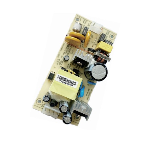
7.4 Appearance of main power supply components
The following is the possible appearance (schematic diagram) of the power supply. The main components may be used alternately, and the bottom pad may be added with plum blossom pad process. The dispensing process (reference) is subject to the actual product.")
8. Circuit diagram")
9. PCB diagram")
")
")
10. Packaging
10.1 Packing drawing
10.3 Loading and transportation experiment
Pilot projects | Test parameters | judgement standard |
Random vibration | Fixed frequency test conditions: vibration amplitude: 4.5mm, vibration frequency: 35HZ, vibration time 30 minutes. Sweep frequency test conditions: Vibration frequency: 10-50HZ, vibration time 30 minutes. | There should be no mechanical damage, disconnection, falling off of components, etc. in the test of the fixed housing of the module, and all indicators should be normal. |
fall | Surface, corner, edge drop: Drop height: 100cm Drop 1 corner, 3 edges and 6 faces each once | The packaged module should be free of mechanical damage, wire breakage, or parts falling off, etc., and all indicators should be normal. |
11. Name tags and barcodes
12. Safety certificate (see attachment)


About

Product
Process
News
Recruitment

 中文
中文 Online consultation
 Online map
 中
中


